-40%
Coherer Detector Marconi Branly Working Replica Spark Gap Radio Receiver
$ 36.93
- Description
- Size Guide
Description
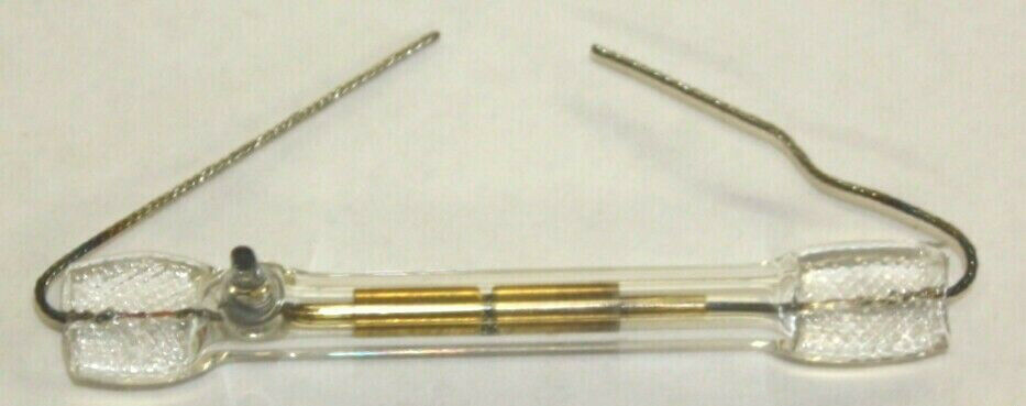
Coherer Detector Marconi Branly Working Replica Spark Gap Radio Receiver. Condition is New. (Note: A small Spark Generator is included)The N-1896 is a modern workingreplica of a Branley / Marconi Coherer Detector radio frequency (RF) detectorfrom 1896. This detector was manufactured to tolerances of .001mm and functionsexactly like a 19
th
century coherer tube. This detector can be usedfor demonstrations or as the main detector for a primitive radio receiver. Inthe early 1900s, Marconi is said to have received three Morse code Dits, theletter “S”, from across the Atlantic Ocean with a coherer tube receiver on theWest, and a spark transmitter on the East.
History of the Coherer:
In 1892 French physicist EdouardBranley first passed RF energy through small quantities of metal filings. Henoticed that the resistance of the metal filings changed when exposed to RFenergy. Branley was one of the first engineers to place the metal filings intoa glass tube with closely spaced electrodes for experimenting. Branley alsotested various metals for the coherer’s gap.
Around 1895 Italian experimenterGuillermo Marconi refined the Branley coherer by optimizing the electrodes, theglass tubing, and the metal filings. Branley was interested in experimenting,but Marconi was interested in long range communications. To this end, Marconidesigned a primitive radio receiver based on the coherer. The coherer detectorwas the first such practical device and they were held in very high regard for10 to 15 years.
Construction:
The Branley or Marconi Coherer isconstructed with two 4mm diameter conductive electrodes (brass) in an evacuatedglass tube. Each electrode face is milled to a matching 15-degree angle and theelectrodes are then separated with a gap that measures .5mm. The gap betweenthe brass electrodes contains a mixture of fine metal filings consisting of 95%pure Nickel (Ni) and 5% pure Silver (Ag).
The wires connecting the brasselectrodes through the glass coherer tube have the same coefficient ofexpansion as the glass to maintain the vacuum. The connecting wires are solidinside the coherer tube, and braided on the outside. The reason for the braidedelectrode wires is that the sensitivity of the coherer detector is adjusted byphysically rotating the device so as to present more, or less, of the metalfilings to the gap in between the electrodes. The more surface area that isexposed to the metal filings, the more sensitive the detector.
When RF energy is presented to thecoherer detector, the metal filings instantly “coherer” and become conductiveto direct current (DC). The Voltage that can be applied to a coherer tubecircuit is very low… somewhere between .5 Volts DC and 3.0 Volts DC.
However, this Voltage is sufficient to drivea “Pony” relay when the coherer is activated. The contacts of the Pony relaycan be used to drive a buzzer, bell, an LED, or a telegraph “Sounder” such asthat used by Marconi.
De-Cohering Your Coherer:
The problem with the coherer tube isthat once activated, the metal filings tend to remain activated in conductingmode until the RF is removed, AND the coherer tube is mechanically tapped. Itcan be tapped lightly with a pencil, or automatically tapped with a mechanicalconnection to the buzzer or bell. The de-cohering process was a detriment tothe speed that the Morse Code message could be sent.
Testing your Coherer Detector:
To test your Marconi – BranleyCoherer detector, simply connect the Red and Black alligator clipped test leadsfrom a Digital Volt Meter (DVM) to the electrode wires from the cohererdetector. The coherer will also work with an analog VOM (Volt Ohm Meter) set tothe 1000 scale. There is no polarity of the coherer to worry about. Set themeter to the 200 Ohm scale, slide the power switch ON, and gently tap thecoherer tube with a pencil to make sure that it is ready for receiving RF. TheOhm reading should be very high, over 20,000 Ohms.
Next, quickly squeeze the ends ofthe fireplace lighter spark generator or a cigarette lighter very near thecoherer detector. You may have to adjust the wire so that a small spark jumpsbetween wire’s tip and the metal end of the lighter. Squeeze the sparkgenerator a few times very close to the coherer detector and the meter shoulddrop down to a reading that is below 100 Ohms. A strong spark will drop themeter down to below 20 Ohms. Notice that this low Ohm reading will remain inplace after the spark as gone.
Now tap the coherer’s glass tubewith a pencil.. and the DVM should reset to read a much higher resistance. Itis this difference between the low Ohm value when activated, and the relativelyhigh Ohm reading when not activated that can be used for radio communications.Repeat the experiment by gently rotating the coherer tube. Notice that thereare more and less sensitive positions. Rotating the coherer tube along thelongitudinal axis is of paramount importance in “tuning” the detector. Thetransmission distance is only a few inches under most conditions.
Increasing the Transmit / ReceiveDistance
To increase the Tx/Rx (Transmit /Receive) distance, one end of the spark generator can be connected to a“Ground” wire and the other end of the spark generator can be connected to an“Aerial” wire. Likewise, one end of the coherer detector can be connected to a“Ground” wire and the other end to an “Aerial” wire. The longer the aerialwires, the greater the Tx/Rx distance. Also, the intensity of the spark isdirectly proportional to Tx/Rx distance. Stronger sparks cause greater RFdisturbances leading to longer distances between the Tx and the Rx sites andbetter radio reception.
Using a 1920s era induction coilfrom the ignition system of an old car will produce a 1cm or greater spark thatcan be picked up at a distance of a mile or more with the coherer. Of coursesuch a distance can only be achieved if both the transmitter and the receiverare connected to earth grounds (i.e. a water pipe, or earth grounding rod) andto elevated, long wire aerials.
Marconi sometimes added RF chokes toboth ends of the coherer detector feeding the Pony relay. The purpose of the RFchokes was to electrically “tune” the receiver so that more than one broadcastcould be received at the same time in the same location. This type of tuningwas not very effective and not very well understood at the time.
By 1905, the coherer was replaced byother forms of detectors that were more sensitive and did not require thede-coherering process after every Morse Code Dit or Dah. By the 1920s, thevacuum tube could detect, as well as amplify, the RF signals and the cohererdetector was relegated to history. It is interesting to note that around 1900,a physics professor from India,
Sir JagadishChandra Bose
, spent years investigating theoptimal design for the coherer. He experimented, as did Marconi, with all sizesand shapes of electrodes and glass tubes. He tried gold, platinum, brass, iron,stainless steel, and many more metal filings. The best material chosen wastypically the 95% Nickel with 5% Silver.
Interesting Coherer 1950s Revival
In the early 1950s, a Japanesecompany, marketing to the US under the name Radicon, designed a remotecontrolled toy robot and a remote controlled toy bus that used a cohererdetector in the receiver.
The batteryoperated, remote control transmitter used a 2mm spark which was received by thebus or robot via Tx antenna and a complimentary Rx antenna.
The first spark from the remotecontrol started the bus or robot with a turn to the right. The second sparkcaused the wheels to travel in a straight line. The third spark caused a turnto the left.. And the fourth spark stopped the action and reset the cohererdetector for the next session. Today the bus and robot commonly sell for0.00 to 00.00 for collectors. Mine still works just fine.
